Will Smith – Director of Software, Adcole LLC
채터와 그 출처란 무엇인가요?
채터는 일정한 간격으로 발생하는 작은 피크 또는 '기복'이 반복되는 패턴으로, 가공된 부품의 마감 표면에 나타날 수 있습니다. Chatter 는 형태 오류(원형 및 로빙)가 아니며, 채터링은 표면 마감 (거칠기)가 아니라 이 두 체제 사이에 존재합니다. 엔진이나 모터의 회전축과 같은 핵심 부품에서 채터는 최종 조립 과정에서 문제를 일으켜 조기 부품 고장을 일으키고 다른 부품을 손상시킬 수 있습니다. 이 문서에서는 샤프트 구성 요소에서 발생하는 채터의 원인, 평가 방법 및 수요가 많은 어셈블리에서 샤프트 품질을 개선하기 위한 측정 결과에 대해 살펴봅니다.
엔진의 소음, 진동 및 거칠기(NVH)의 주요 원인인 채터는 적절한 품질 공정과 장비를 통해 발견할 수 있습니다. 채터는 밀링, 터닝, 보링, 연삭 등과 같은 모든 가공 작업에서 발생할 수 있습니다. 보다 구체적으로, 채터는 일반적으로 공구 불균형, 툴링 또는 고정 강성 부족, 비등방성 부품 강성(크랭크샤프트의 특정 문제), 원형 외곽 부품 센터, 오작동 또는 마모된 장비 및 기타 불균형 또는 진동의 원인으로 인해 발생합니다.
채터 검사가 중요한 이유
Modern motors and internal combustion engines (ICE) demand tighter tolerances and higher performance, making efficiency and longevity crucial. Rotating shafts with chatter patterns can cause excessive noise and vibration issues within the final assembly of an engine or motor, potentially leading to NVH concerns that could require recalls, which can lead to customer dissatisfaction, reputational damage, and loss of sales. This is particularly true in high RPM requirements such as EV rotor shafts, which can reach 20,000 RPM or more.
Chatter is a feature that has been measured and analyzed by manufacturers for decades, but is also overlooked when designing a new part. Whether for engines or motors, this parameter can be critical to monitor. While production machines are often prioritized in budgets, quality control equipment is equally important. Poor quality can be costly, so engineers and production managers must develop robust quality control systems and ensure they have the right equipment to measure necessary features.
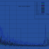
연삭 휠 또는 절삭 공구의 회전 속도와 공작물 회전 속도의 비율과 관련된 특정 주파수에서 채터가 발생하는 경우가 많습니다. 그 결과 프로세스의 '고유 주파수'는 일관된 시그니처를 나타내며, 주파수 도메인 플롯에 더 높은 고조파가 존재하는 경우가 많습니다. 공정 파라미터를 조정하여 이 '고유 주파수'의 진폭을 제어하거나 제품 요구 사항에 맞게 고유 주파수가 발생하는 주파수를 변경할 수 있습니다. 이 주파수에서 진폭 값이 증가하거나 다른 주파수에서 추가 진폭 스파이크/피크가 발생하면 프로세스 관련 문제 또는 외부 영향을 나타내는 경우가 많습니다. 외부 영향에는 근처의 모터, 펌프, 기타 장비(예: 스탬핑 또는 프레스 기계) 또는 지게차 통행이 포함될 수 있습니다. 채터 출력은 기술자와 엔지니어에게 문제의 원인을 안내하여 제품 품질을 수정하고 복원하는 데 도움이 될 수 있습니다.
잡담을 검사하는 방법
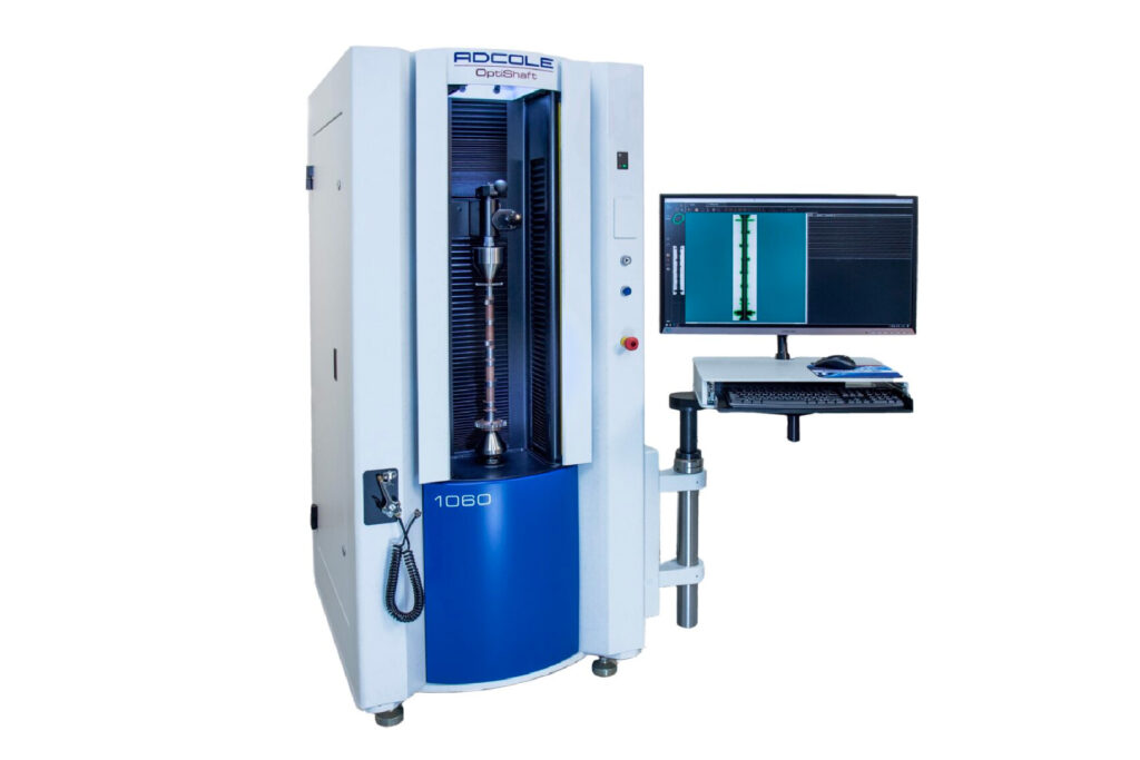
장비
Quality control machines are optimized to measure a specific set of parameters; for example, a precision tactile machine can often measure chatter, while an optical machine cannot (or not as effectively). Chatter is not something that would be detected by evaluating standard GD&T features like roundness or refinements of roundness data such as sector roundness or lobing. The amplitude can be quite small at sub-micron levels, the chatter may be limited to a single area, and the frequency of the chatter may vary significantly. However, regardless of the amplitude, region, or frequency variations, chatter can still have a discernible impact on the quality, final assembly, and performance of ICE or electric motors.
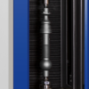
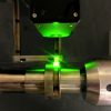
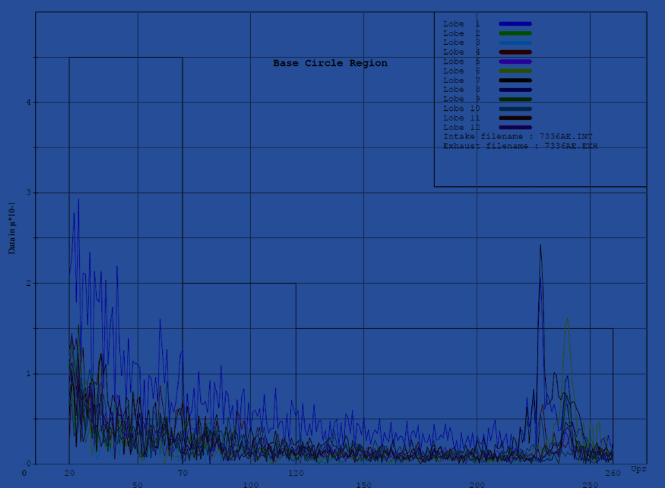
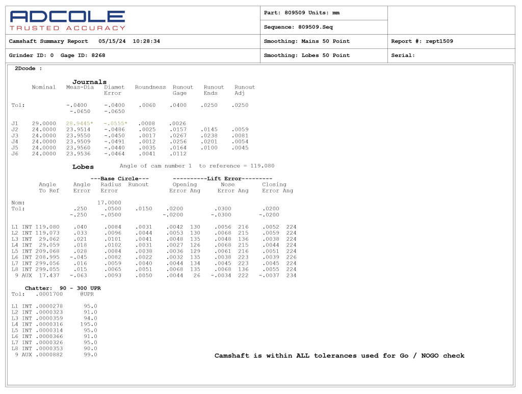
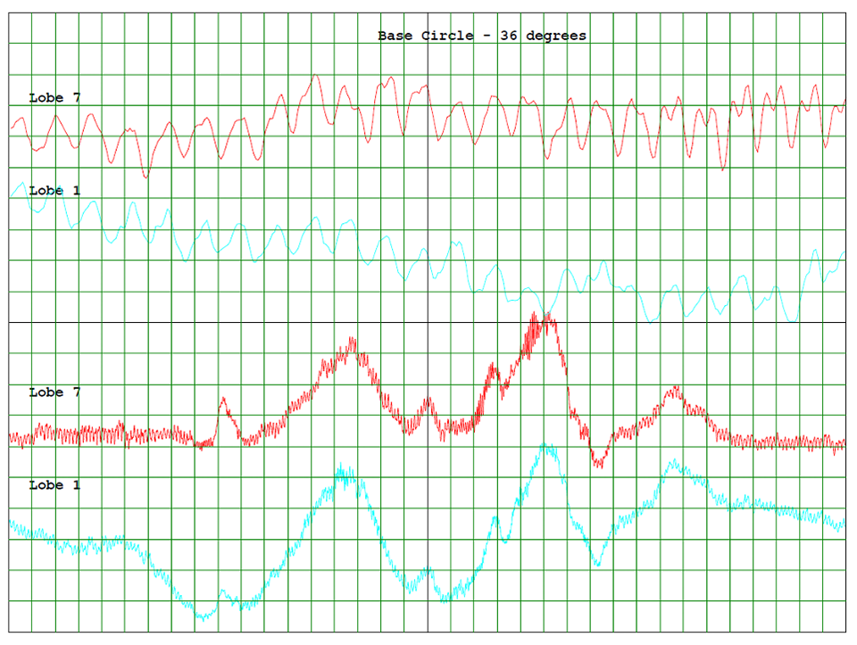
하나 tool for measuring chatter on shafts after a grinding process would be an Adcole tactile shaft metrology gage. These gages, along with proper software that can measure a wide range of GD&T parameters, provide valuable data and analysis to maintain the demanding quality required for rotating shafts. In the camshaft world, analysis of a lobe base circle region where the grinder velocity would be uniform over a constant radius provides a cleaner signal for detecting a chatter issue. The lift region of the lobe where radii rapidly changes could be analyzed separately, providing additional information over the surface that would have been ground with an adjustable velocity.
평가 방법
"또한 많은 진동 관련 문제가 특정 주파수에서 발생하기 때문에 특정 주파수에서 진폭의 변화를 기반으로 진동의 원인과 위치를 좁히거나 식별할 수 있습니다.” (Collins D., 2022) This is why calculating amplitude over a frequency domain is better than simply counting lobes or peaks within the profile error.
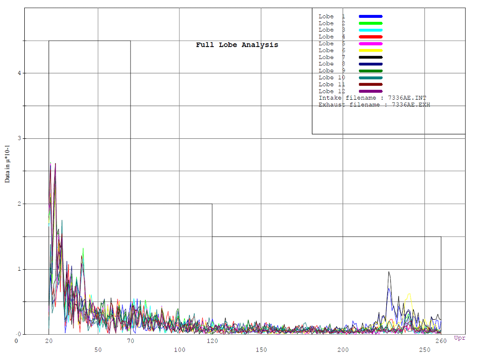
모든 측정 데이터는 데이터 수집 소프트웨어로 직접 전송되어 시간 파형이라고 하는 진폭 대 시간 또는 고속 푸리에 변환(FFT)이라고 하는 진폭 대 주파수 또는 두 가지 모두로 신호를 기록합니다. 이 모든 데이터는 컴퓨터 프로그램 알고리즘에 의해 분석되며, 엔지니어 또는 숙련된 진동 분석가가 이를 분석하여 기계의 상태를 파악하고 느슨함, 불균형, 정렬 불량, 윤활 문제 등과 같은 임박한 문제를 식별합니다. 진동 분석은 휠 불균형이나 휠 드레싱 문제와 같은 문제를 감지할 수 있습니다.
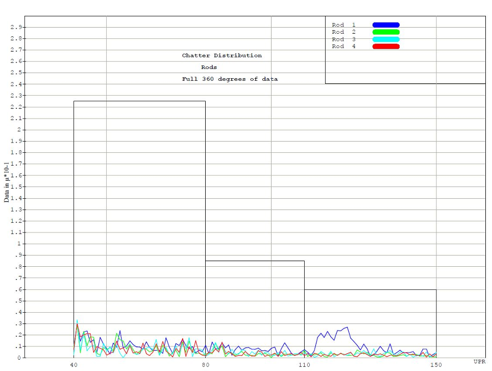
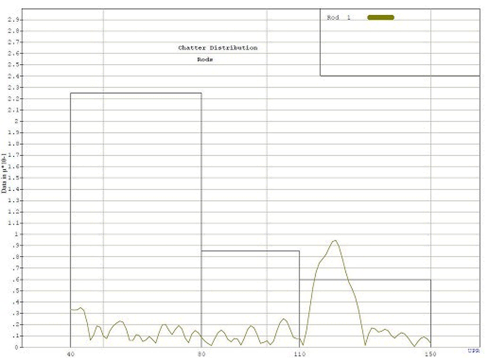
Chatter can also mask itself on a shaft journal by showing up only over a small angular range. This makes it more difficult to measure and detect. Another method is the quadrant analysis option that can be used for journals on any rotating shaft. This allows for the entire 360 degrees of roundness data to be analyzed for chatter, and it breaks the roundness error into four 90-degree regions for chatter analysis. This analysis option provides a tool that can pick up a “chatter burst” on the surface of a journal where during the production process, a region of usually less than 90 degrees exhibits a pattern of undulations. The amplitude of these undulations is frequently too small to affect the roundness or even lobing measurement parameters, but can still cause issues with NVH in the final assembly of the engine. By analyzing the roundness error over 90 degrees, it is possible to measure a higher amplitude of chatter that may exceed the defined tolerance.
제한된 각도 범위에서 채터를 찾는 한 가지 방법은 '슬라이딩 윈도우' 방법을 사용하는 것입니다. 이 방법을 사용하면 각도 창을 각도 단위로 설정하고 슬라이드 각도 증분을 설정할 수 있습니다. 이 슬라이딩 윈도우는 360도 전체 진원도 또는 프로파일 오류 데이터를 검토하여 최대 진폭과 이 문제가 발생한 각도 영역을 결정합니다. 또한 필요한 테스트를 통해 특정 각도 영역에 대한 채터 허용 오차와 채터 범위를 분석할 수 있어야 합니다. 이는 알려진 "노이즈가 있는" 샤프트에 대해 일련의 테스트를 실행하고 이를 알려진 "조용한" 샤프트에 대한 동일한 일련의 테스트와 비교하는 것을 기반으로 할 수 있습니다.
채터 측정값 출력
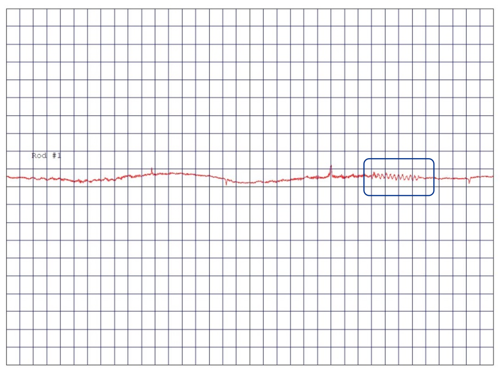
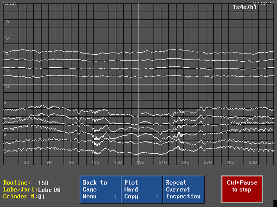
부품 표면에는 다양한 방식으로 채터가 나타날 수 있습니다. 때로는 큰 각진 창에 나타나며 깨끗한 주파수를 가질 수 있습니다. 이는 측정 중인 특정 요소의 진원도 또는 프로파일 오차 플롯에서 잠재적으로 볼 수 있습니다. 그러나 진원도 또는 프로파일 오차 플롯에서는 종종 오차 데이터에 필터를 적용하여 채터를 숨길 수 있으므로 채터가 마스킹될 수도 있습니다.
In Figure 2a에는 저널 진원도 및 캠축 로브 프로파일 오차에 대한 오차 플롯이 있으며, 플롯 하단에 6개의 로브가 있습니다. 이 로브 프로파일 플롯은 0-90도 및 270-360도 사이의 기본 원 영역을 보여줍니다. 리프트 영역 오차는 90~270도입니다. 이 예에서는 기본 원 영역에서 명확한 기복 패턴을 볼 수 있습니다. 기본 원은 반경이 일정하기 때문에 일반적으로 일정한 속도로 접지되지만 리프트 영역에서는 그렇지 않습니다.
일부 기업에서는 제조 공정의 문제를 파악하기 위해 로브 카운팅 프로세스를 사용합니다. 이는 부적합을 나타내는 진원도 또는 프로파일 오류의 각도 영역을 파악하는 데 유용하지만, 로브 또는 피크가 어떻게 정의되는지에 대한 내부 정의에 의존하여 카운트할 수 있다는 약점이 있습니다. 이 방법은 일반적으로 피크 사이의 등간격을 찾지 않으므로 특정 발생 빈도를 확인할 수 없습니다.
결론
부품 마모나 고장을 빠르게 유발할 수 있는 소음과 진동 없이 오랜 기간 작동하는 고품질 샤프트를 일관되게 생산하려면 채터를 측정하는 것이 중요합니다. 고속으로 회전하는 정밀 회전 부품에서 측정 가능한 진동이 발생하면 엔진 또는 시스템 고장으로 이어질 수 있습니다. 정의된 영역의 표면 채터를 살펴볼 수 있는 고급 분석 옵션이 있는 도구를 사용하면 제품이 출고되기 전에 제조상의 문제를 감지할 수 있습니다. 샤프트 제조업체는 인라인 또는 감사실 환경에 적합한 품질 도구 또는 게이지에 투자하여 지정된 허용 오차를 벗어난 제조상의 잠재적 오류를 분석하고 이를 수정하기 위한 조치를 취할 계획을 세워야 합니다.
Collins, D. (2022, October 17). How are fast Fourier transforms used in vibration analysis. Motion Control Tips. https://www.motioncontroltips.com/how-are-fast-fourier-transforms-used-in-vibration-analysis/