Adcole 3D Color Map Software Helps Automotive Manufacturers Spot Defects
Adcole LLC
Detecting manufacturing defects late in the production process is costly for quality control. To help automotive and machine manufacturers quickly identify defects, tolerance deviations, and nonconformities that may not be readily apparent in traditional geometric defect reports and charts, Adcole has developed 3D Color Map software.
3D Color Map is a powerful, state-of-the-art analysis tool that provides a completely new method for analyzing and evaluating roundness, profile errors, size errors, runout deviations, and complete ratchet noise on Adcole’s 911 series, 1100 series, 1200 series and 1300 series shaft measuring gages.
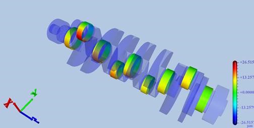
The 3D Color Map tool provides insights into manufacturing challenges such as grinding, polishing, porosity, material build-up, or shape problems
The integration between 3D Color Map and Adcole measuring instruments is seamless. The software can be installed on both an Adcole measuring instrument and a separate PC workstation. The high-resolution data with an accuracy of 1/10º captured by an industry-standard Adcole measuring device can be displayed and interpreted within seconds using 3D Color Map. This gives measuring device customers completely new insights into manufacturing and quality issues such as potential grinding, polishing, porosity, material build-up, or shape problems.
With 3D Color Map software, manufacturers can analyze and evaluate roundness, profile errors, and size errors, as well as perform runout deviations and complete ratchet analyses.
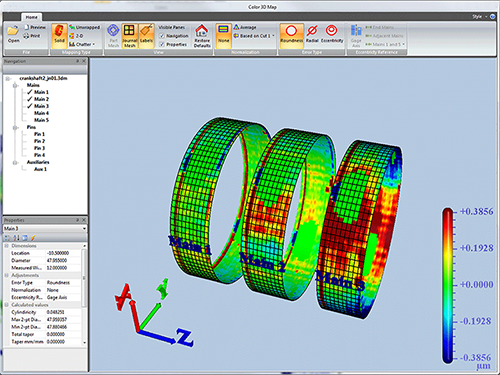
The 3D Color Map user interface is familiar to anyone who has worked with a common CAD/CAM package, but it is equally easy to use for inexperienced users. The screen displays a high-resolution, shaded 3D image of the customer’s part, powered by a very fast, industry-standard OpenGL graphics rendering engine. The 3D image of the part can be dynamically rotated, moved, or enlarged with simple mouse clicks and drags. The measurement results and the opacity of the part can also be dynamically scaled, and alternative views of features or feature groups are available. The software supports countless options for customizing the analysis, isolating roundness, radial, and eccentricity errors, and fixing hidden problems. The results of the analysis can be printed in easy-to-understand reports that include a summary of the part, the dimensions, and the calculated measurement parameters for the selected part elements.
With 3D Color Map software, manufacturers can analyze and evaluate roundness, profile errors, and size errors, as well as perform runout deviations and complete ratchet analyses.
The 3D Color Map user interface is familiar to anyone who has worked with a common CAD/CAM package, but it is equally easy to use for inexperienced users. The screen displays a high-resolution, shaded 3D image of the customer’s part, powered by a very fast, industry-standard OpenGL graphics rendering engine. The 3D image of the part can be dynamically rotated, moved, or enlarged with simple mouse clicks and drags. The measurement results and the opacity of the part can also be dynamically scaled, and alternative views of features or feature groups are available. The software supports countless options for customizing the analysis, isolating roundness, radial, and eccentricity errors, and fixing hidden problems. The results of the analysis can be printed in easy-to-understand reports that include a summary of the part, the dimensions, and the calculated measurement parameters for the selected part elements.

The 3D color map supports countless options for customizing the analysis, isolating roundness, radial, and eccentricity errors, and fixing hidden problems. Even chatter can be displayed in 3D.
The new measurement software requires an operating system with 32/64-bit versions of Windows 7 or higher, an Intel i5 processor with 2.6 GHz and 4 GB or equivalent graphics hardware with integrated OpenGL support such as Intel HD Graphics, and a screen resolution of 1280 x 1024.