
How Gage-to-Grinder Compensation Fixes Precision Shaft Surface Problems
Adcole LLC
Camshafts, crankshafts, and other precision rotating shafts live and die on microns. A journal that’s a few tenths of a micron out of round, a lobe with the wrong lift profile, or a surface with the wrong roughness profile can turn a finished part into scrap, after all the time and material has already gone into it.
The traditional way of catching these problems (measure, generate a report, walk it to the grinder operator, adjust by hand, hope it holds) leaves a gap between inspection and correction. Bad parts can pile up in that gap before anyone notices a trend. Here’s what typically goes wrong on a grinding line, and how a measurement-to-machine loop solves it.
Why Grinders Drift Out of Spec
Grinding is a subtractive, contact-based process, and every one of its physical inputs (wheel, spindle, coolant, workpiece) degrades or fluctuates during a production run. That produces a handful of recurring failure modes on precision shafts.
CHATTER AND LOBING
Chatter is a repeating, undulating pattern of marks left on the shaft surface, caused by vibration between the grinding wheel and the workpiece as material is removed. It’s especially damaging on camshafts and crankshafts because it shows up as a periodic error at a specific number of undulations per revolution (UPR), a signature that’s often invisible to the naked eye but translates directly into noise, wear, or fatigue failure once the part is in an engine. Chatter is notoriously hard to prevent, because its root causes, including spindle bearing wear, wheel imbalance, belt resonance, and mounting looseness, are usually only visible after the part comes off the machine already out of spec.
WHEEL WEAR AND DIMENSIONAL DRIFT
A grinding wheel doesn’t cut the same on part 500 as it did on part 1. As the abrasive wears and the wheel diameter shrinks, effective infeed changes, and journal diameters, cam lobe lift, and taper begin to drift. The drift is slow at first, then faster as the wheel approaches its dress limit. Left unmonitored, it walks a process from the center of its tolerance band to the edge of it, and eventually out of it, without any single event that would trigger an operator to step in.
THERMAL GROWTH
Grinding generates heat at the interface of the wheel and workpiece, and both the shaft and the machine structure expand as a shift progresses. A machine that’s perfectly zeroed at the start of the day can produce parts with a systematic diameter or profile offset by mid-shift, purely from within the manufacturing environment or coolant temperatures causing thermal expansion of the spindle, guide rails, and fixturing. This is a slow-moving error that’s easy to miss because no single part looks obviously wrong. It’s the trend across the run that matters
LOBE AND JOURNAL FORM ERRORS
On camshafts specifically, lobe lift error, base circle runout, and profile error in the ramps and/or flanks all affect valve timing and engine performance. Small form errors in the grind, such as a slightly wrong contour on the nose of a lobe or an asymmetric taper on a journal, don’t always fail a simple diameter check, but they still affect how the part performs once it’s running. These errors are among the hardest to catch with anything less than full-profile, high-density measurement.
SURFACE ROUGHNESS INCONSISTENCY
Even when geometry is in tolerance, surface finish can wander. A fresh wheel produces a different roughness signature than a worn one, and inconsistent surface texture affects oil retention, wear rate, and noise, vibration, and harshness (NVH) performance downstream. Surface roughness problems are particularly frustrating for manufacturers because dimensional checks alone won’t catch them. A part can be perfectly round and perfectly sized and still have a surface finish that causes premature wear in the field.
THE COMMON THREAD
Every one of these problems shares the same underlying issue: the grinder has no memory. A CNC grinding cycle runs the same program regardless of what the wheel, spindle, or workpiece actually did last time. Without a measurement system feeding part data back into the process, the machine is only as accurate as the day it was last manually adjusted, and every variation in the system over time starts eroding that accuracy the moment production starts.
How Gage-to-Grinder Compensation Works
A high-precision cylindrical coordinate measuring machines (CCMM) sits at the exact point where this feedback loop needs to close: immediately after grinding, at production speed, measuring the full geometry of the part rather than a handful of sample points.
High-Density Measurement
After grinding, the part is loaded onto a gage which can scan the full 360° profile of each journal or lobe, capturing form, lobe lift profile, chatter, and size data in a single pass rather than a spot check.
Deviation Analysis
Analytically driven and capable gage software compares the measured profile against the part’s nominal geometry and tolerance bands, isolating the specific error, whether it’s a diameter offset, a taper, a UPR chatter signature, or a lobe asymmetry, rather than simply returning a pass/fail result.
Compensation File Generation
Instead of stopping at a report, the software converts that deviation data into a compensation file: a structured correction dataset formatted for the grinding machine’s controller, specifying exactly how the next grind cycle needs to shift (infeed position, axis offset) to cancel out the measured error.
Feedback to the Grinder
The compensation file is passed to the grinding machine, which applies the correction on the next part or the next batch. Where wheel wear or thermal drift is gradual, this creates a running correction that tracks the process instead of letting it wander toward the tolerance edge.
Continuous Verification
Because every part, or a high-frequency sample, is re-measured after grinding, the loop keeps correcting itself. The gage isn’t just checking quality; it’s actively steering the process.
Why This Beats a Standard Pass/Fail Check
It catches drift before it becomes scrap.
Because wheel wear and thermal growth are gradual, closed-loop compensation corrects small deviations continuously instead of waiting for a part to fail and reacting after the fact.
It targets the specific error, not just the symptom. A compensation file can carry axis-specific, angle-specific correction data for individual journals or lobes, so roundness on a journal or a profile error in the ramps and/or flanks gets corrected precisely, rather than applying a blunt, whole-part offset.
It shortens the diagnostic path for chatter. Chatter is normally only visible after the part is already made, which is what makes it so hard to prevent. Frequency-based analysis of the measured error data lets engineers pinpoint the UPR signature tied to a specific mechanical cause, such as spindle bearing wear, wheel imbalance, or belt resonance, and correct it before the process produces more out-of-spec components. That improves efficiency, reduces scrap costs, and maximizes grinder uptime.
It removes operator variability. A compensation file applies a data-driven correction consistently, rather than relying on an operator’s judgment call about how much to nudge a dial.
It protects capital equipment investment. Continuous, data-driven correction helps qualify grinders and machining tools against a known standard and catch quality breaches early, extending useful wheel and dress life and reducing unplanned downtime for full recalibration.
Closed-loop compensation catches drift before it becomes scrap. Because wheel wear and thermal growth happen gradually, this approach corrects small specific deviations continuously rather than waiting for a part to fail and reacting after the fact with a whole offset correction. This precision extends to chatter as well, which normally only becomes visible after a part is already made, making it notoriously hard to prevent. Frequency-based analysis of the measured error data lets engineers pinpoint the UPR signature tied to a specific mechanical cause, such as spindle bearing wear, wheel imbalance, or belt resonance, and correct it before the process produces more out-of-spec components, improving efficiency, reducing scrap costs, and maximizing grinder uptime.
Adcole's Approach
While an Adcole gage can close this loop and improve the process and finished product, an Adcole gage doesn’t communicate directly with the grinder controller; instead, it writes a filtered roundness data compensation file after each measurement, keeping only the latest files (a configurable setting) in a consistent format that avoids version-mismatch issues. The software then pulls those latest files and averages them into a single correction file sent to the grinder when correcting for roundness error, which both smooths out noise and prevents any one part’s reading from causing overcorrection. An Adcole gage can write out three types of compensation files for errors: Pin journal roundness, lobe profile error array, and in some cases solutions for diameter feedback.
PIN JOURNAL ROUNDNESS
Pin journal roundness compensation corrects the cross-sectional shape of a cylindrical journal, the part of a crankshaft where the connecting rod bearing rides. The Adcole gage measures radial deviation around the circumference at one or more axial positions and finds how far the section departs from a true circle. The compensation file is a correction as a function of angular position. During grinding, the machine modulates the wheel infeed in sync with the workpiece rotation so it removes slightly more or less material at each angle. This offsets the systematic sources of roundness error, such as spindle or steady-rest runout, thermal drift, work-holding deflection, or the eccentric motion inherent in orbiting a pin journal. Because it’s aimed at a circular form, the correction is usually small in amplitude (microns) and is tied to the rotational angle of the part. Filtered roundness data means thermal drift, which affects size, not roundness, doesn’t interfere and bad readings are screened out before being used for correction. Because corrections are size-independent, size calibration has no bearing on them.
LOBE PROFILE ERROR
Lobe profile error array applies to camshafts (or similar non-circular parts), where the surface is intentionally non-round. Here the Adcole gage compares the measured profile against the nominal lift-versus-angle specification and records the deviation at each angular increment, typically stored as a table (array) of error values across the full 360° or across the lobe’s flanks, nose, and base circle. The compensation file feeds those errors back to the grinder’s CNC, which adjusts the programmed wheel position/X-axis motion point by point so the next part’s profile more closely matches the design. The key difference is the reference: roundness compensation corrects deviation from a perfect circle, while the lobe profile error array corrects deviation from a prescribed, non-circular target curve. As a result, the lobe array is generally denser and tied to the part’s design geometry that matter for engine performance continuity such as lift, velocity, and acceleration, while roundness compensation targets a simpler, shape-agnostic form error.
In effect, Adcole’s gaging system closes the gage-to-grinder gap: measurement data comes off the gage, is translated into a compensation file, and feeds back into the grinding machine’s controller so that the next part, or sometimes the very next cycle, is corrected before it’s cut. Beyond correcting errors, this approach removes operator variability, since a compensation file applies a data-driven correction consistently rather than relying on an operator’s judgment call about how much to nudge a dial. It also protects capital equipment investment: continuous, data-driven correction helps qualify grinders and machining tools against a known standard and catch quality breaches early, extending useful wheel and dress life and reducing unplanned downtime for full recalibration. The main benefit of the part feedback process is reduced scrap through improved part quality.
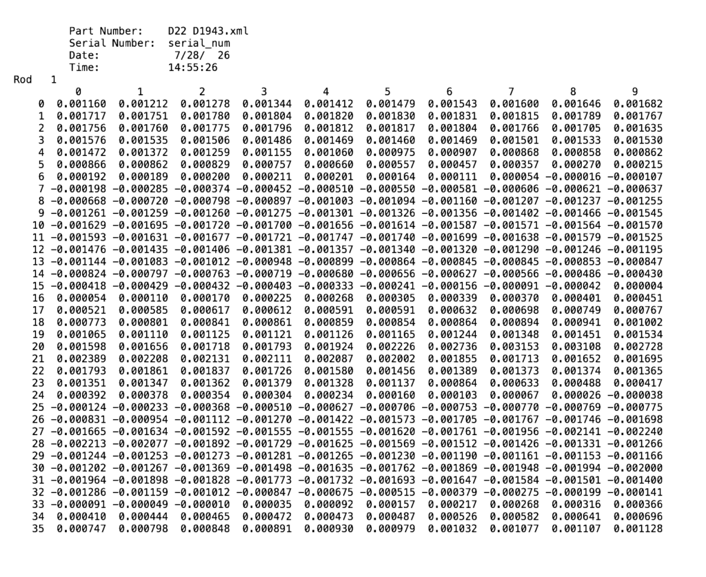
Roundness error from Rod 1 in whole degree format, values in mm.
The Bottom Line
Bad grinder performance on precision shafts is rarely one big failure. It’s the accumulation of small, physically inevitable drifts: wheel wear, thermal growth, vibration, and form error creeping in a little at a time. A gage that only reports pass/fail after the fact can tell you a part is bad, but it can’t stop the next one from being bad too. A true gage-to-grinder loop, combining measurement, deviation analysis, and an automatically generated compensation file feeding back into the grinder’s controller, turns inspection from a scrap detector into a live process control system, holding the grind on target part after part instead of letting it wander until someone notices.
Related Gages & Software