Parallelism
Adcole LLC
Because the coordinates for parallelism errors depend on the position of the part relative to the dimension components, some operators may find this confusing. This post helps clarify some frequently asked questions you may have about parallelism. First, we define parallelism, then we discuss the coordinate system.
Journal parallelism is based on the radial measurements of the two outer cuts of the journal. The calculation compares the Least Squares Center (LSC) of cut 3 with the LSC of cut 1 to determine the axis of the specific journal and then compares this journal axis with the reference axis. The reference axis, or reference point, is based on the average middle components of the outer cuts (cut 1 and cut 3) of the reference days. The reference axis is usually the end journals or adjacent journals, but it can also be the gauge axis or a specified axis based on selected journals. In some measurement models, the reference axis can be redefined.
The parallelism to the journal can be influenced by the width of the journal or the distance between the outer cuts. The parallelism is not influenced by the radius of the journal. Linear scan data can be analyzed relative to a part axis to provide an alternative parallelism calculation.
After the parallelism has been measured, you can view the output error in two different ways: as absolute parallelism values, including the angle at which it occurs, or as X and Y parallelism values. The first method gives the vector component of the parallelism; the second method gives the individual components of the parallelism.
Adcole has specified the coordinate system for current software versions as follows: the y-axis corresponds to the follower movement as it extends, and the x-axis is perpendicular to this follower movement.
When viewing the rotation axis, positive x moves from the rotation axis into the stone, positive y moves from the rotation axis into the follower.
The coordinate system is the same when a crankshaft is measured in a counterclockwise or clockwise rotation.
The orientation of the part is with Main 1 at the end of the head and Main N at the end of the loose head.
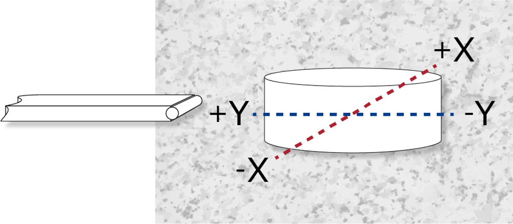
Follower (left)
The X- and Y-axes are on the same plane and perpendicular to each other. The X-axis is perpendicular to the stone and the Y-asix is parallel to it.
Although reversed parts physically differ in the way the coordinate system is displayed, your output data remains consistent regardless of the orientation of the parts in the dimensioning. Reversed parts are measured in the opposite direction of rotation, such as when the part is placed in the dimension with head 1 at the head. The software takes this information into account when calculating parallelism and reports identical output.
- Be careful when measuring parallelism
- Parallelism can be affected by problems with the part centers
- Parallelism can be affected by driver program issues